Leaderboard

Popular Content
Showing content with the highest reputation on 04/13/2014 in all areas
-
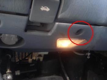
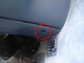
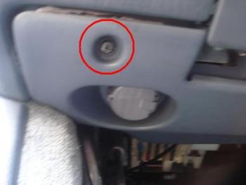
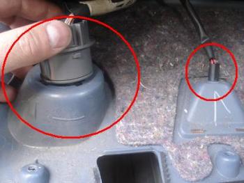
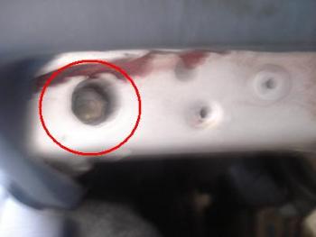
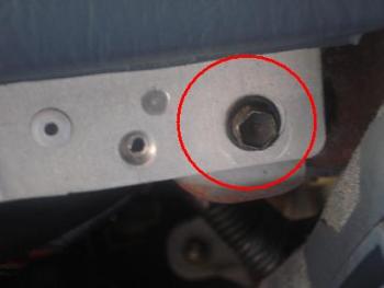
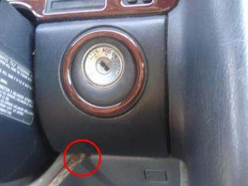
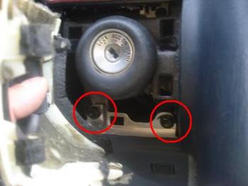
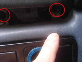
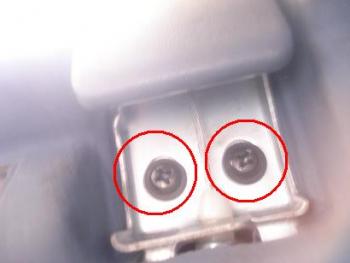
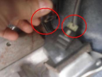
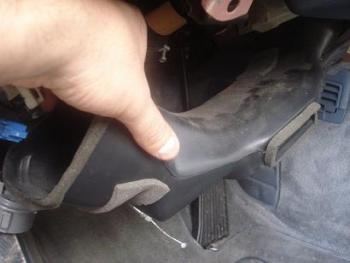
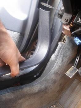
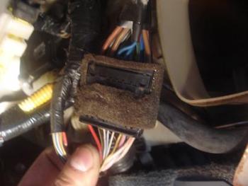
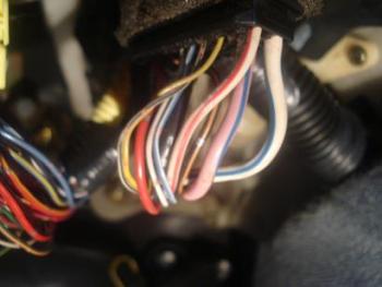
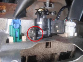
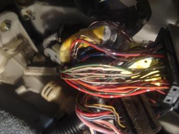
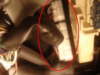
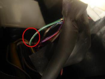
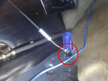
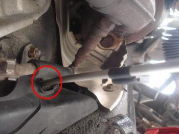
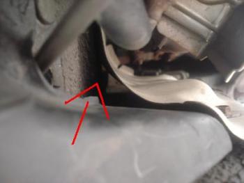
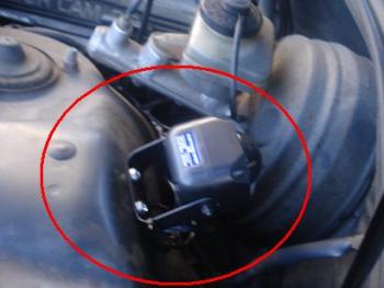
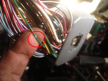
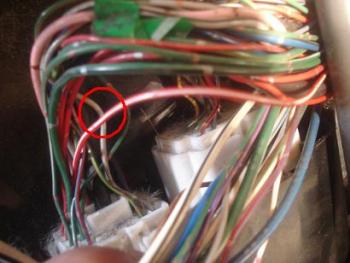
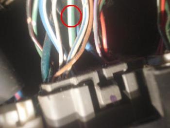
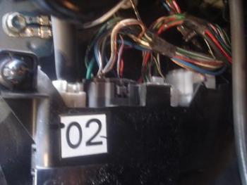
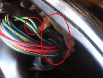
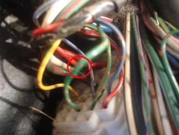
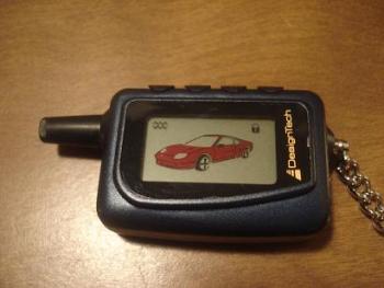
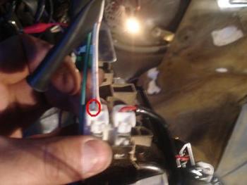
OK....MY REMOTE START/SECURITY SYSTEM/KEYLESS ENTRY/TRUNK POPPER--HAS OFFICIALLY BEEN INSTALLED BY MYSELF WITH SOME HELP AND ENCOURAGEMENT FROM MEMBERS OF THIS FORUM! SYSTEM INSTALLED: READY REMOTE (DESIGNTECH) MODEL # 20092 TIME SPENT: 4HRS INCLUDING PICTURES + 1HR SPENT...TO RECONFIGURE DOOR LOCKS-(I WILL EXPLAIN LATER) PLEASE KEEP IN MIND THIS IS MY FIRST ALARM INSTALL!! OK...SO HERE WE GO: TOOLS I USED: PHILIPS HEAD SCREW DRIVER 10MM SOCKET/WRENCH ELECTRICAL TAPE WIRE TIE DRILL-FOR HOOD PIN SWITCH -YOU MAY CHOOSE TO USE THE SAME WIRE THAT THE FACTORY ANTI-THEFT USES. WIRE SPLITTER (TO SPLIT WIRE "WITHOUT" CUTTING IN IN HALF) VEHICLE WIRING INFORMATION - I WILL TELL YOU COLORS OF THE WIRES I USED--BUT PLEASE TEST THEM!! MULTIMETER - OR SOMETHING TO MEASURE/TEST THE POLARITY OF THE WIRES. SOLDER/SOLDERING IRON - I ONLY USED IT ON THE MAIN WIRES! -POWER/IGNITION ETC.. I started by removing the bottom half of the underdash held in place by 5 philips head screws. 3 on top (pictured) 2 at the bottom. after taking all the screws out....unplug the ECU diagnostic plug (at least I think that' what it is) and the courtesy light (pictured) by turning counterclock wise and pulling them out. Once you take the bottom of the underdash you will discover 2 10mm screws at each end of the bottom of the upper half of the undersdash. Take them out! The upper half is held in place by 6 10mm screws 2 at the bottom and 4 at the top. BEFORE REMOVING THE TOP 4 SCREWS UNSCREW THE HOOD RELEASE WIRE- It's held in place by 2 philips head screws-take them out and then release the wire. The 4 top screws are located 2...right bellow the parking brake release handle and the other 2 are bellow the ignition/lock cylinder (you need to pry out the plastic piece sounding the key switch)--please see pictures. BEFORE--pulling this part out....pull out what looks like a little vacum hose and a 2-wire white harness from behind this section. AND also take out the plastic piece where the Gas and Trunk release switch are mounted, which is held in place by 2 philips head srews. Now, remove the plastic air vent tube and the plastic trim piece at the bottom of the the diver's side door frame. OK HERE COMES THE FUN PART!!! behind the lock cylinder, right next to where the air vent tubing was......you will find a black harness with thick wires, this is your main harness. Notice that the colors of some of the wires change from one end of the harness to the other...for this specific install I used the ones on the bottom of the harness (see pic)... The colors, polarity and functions are as follows: 12V POWER - positive - WHITE/BLUE START - positive - RED/SILVER DOTS * IGNITION 1- positive - BLACK/ORANGE * IGNITION 2 - positive - BLACK/YELLOW ** ACCESSORY - positive - PINK/BLUE * My aftermarket system came with a starter kill-wire (not even I with the key can start the car if the system is armed) a relay was used and the start & Ignition1 wires were used. This is an optional feature that I did not need to install but I choose to. Some aftermarket systems do not have this feature and even if it does you don't have to use it if you don't want to. Instructions on how to do do this should be included the manual that came with your system. ** Although most aftermarket alarms do have a positive (+) Ignition2 wire output - The Ignition 2 wire from my aftermarket system was negative (-) so I had to use a relay to turn it into a positive (+) The manual your aftermarket system came with should tell you if you need a relay or not and also how to use it. If you need more info let me know. The following 2 wires (Horn and Hood pin) I will tell you what the wiring guide says about them but I did not use them nor tested them so you will have to that yourself. I'll tell you why I chose not to use them later. The colors, polarity and functions and location acording to most wiring guides I found are as follows: Horn - negative - green/red - steering column The following picture is of the harness to the right side of the steering column where most wiring guides will tell you the Horn wire is...however, they said the same thing about the parking light wire and I could not find that wire here...I'll show you where I found it later. Also, please note the the Horn wire is NEGATIVE and my system has a POSITIVE horn wire output so if I wanted to use the horn I would have to use a relay AGAIN.... and I did not have any more relays at hand, besides I do like the sound that the siren that came with the system has so I decided to run a wire to the front engine compartment for the siren. I'll show you how later. Hood pin - negative - green/white - anti-theft module The following pictures is of the harnesses at the anti-theft module. The anti-theft module is located at the top left hand side corner under the driver's side dash behind the fuse box. I chose not to use this wire because it seemed very thin and hard to get to and I was not comfortable stripping the plastic piece and attaching another wire to it (you can use wire attachement clips but I did not have any) besides, I was already runnig a wire to the engine compartment for the siren so I decided to run the wire for the hood pin too! By the way, you may run the TACH wire at the same time too (if you choose the tach options on your starter). OK...since I was talking about running wires to the engine compartment here is how I did it. There is a plastic groumet under the carpet right by where the brake pedal is so I took the groument out, inserted a long screw driver all the way to under the car (there is another plastic groumet there)....attached 2 wires to it and pulled it back up-inside the car. I ran the wires from under the car along the side under a metal heatshield plate all the way up by the brake fluid container(SEE PICS). Make sure to insulate your wires so they won't be affected by the heat....I used tape around the wires and also wire loom. Once the wires are in the engine compartment I plug one of them to the positive side of my siren, screw the siren inplace and grounded it. The other wire I ran to where I had drilled and installed my hood pin switch and connected it there. Inside the car I connected the wire from the siren to the POSITIVE siren output from my aftermarket system and connected the Hood pin switch to the NEGATIVE hood pin switch input in my aftermarket system. I DID NOT USE A TACH WIRE! Ok...NOW WE ARE WORKING INSIDE THE CAR AGAIN......WE ARE HALF WAY THERE!! I NEED A DRINK-- Some of the following wires are in the locations most wiring guides (I looked at) indicated, some are not! ---I will indicate which ones the wiring guides I looked at were wrong about! THESE ARE THE PLUGS AT THE BOTTOM OF THE DRIVER'S SIDE KICK PANEL! The following are the wires and locations I used! The colors, polarity functions and location I USED are as follows: Trunk Release - negative- at trunk release switch! (I used the blue wire in the top 2wire harness) Parkinglight - positive - green/sliver dots - wire bunch coming out from fuse panel -guides were wrong about his one! Door trigger - negative - red/white - third plug from left to right at the driver's side kick panel - guides were right! Brake - positive - green/white - second plug at the driver's kick panel (gray plug) - guides were right! OK--THE FOLLOWING INFORMATION PLEASE READ CAREFUL!!! ONCE AGAIN...THIS IS BASED ON MY INSTALLATION AND MY PERSONAL EXPERIENCE....WIRING GUIDES MAY DIFFER FROM WHAT I DID! CHECK YOUR MANUAL AND TEST ALL WIRES!! I found 5 wires that have to do with the lock/unlock and anti-theft system arm/disarm. I only tested 3 at first but then find out I needed to test more!! BY THE WAY...WE HAVE NEGATIVE DOOR LOCKS! There is a BLUE harness on the diver's side kick panel (next to a small white one) - They both hold all the wires coming into the car from the driver's side door. (I circled the wires I used in my final installation...not circled is the green/black "unlock" wire) On this BLUE plug you will find a Green/black wire - this is the unlock wire using the control switch - it showed no changes when using the key. (This were the first wires I tested and they seemed right so I used them first--did not test any more.) Green/red wire - this is the lock wire using the control switch - it showed no changes when using the key. (This were the first wires I tested and they seemed right so I used them first-did not test any more.) Grenn/yellow wire - this wire is the lock wire using the key and the FACTORY ALARM "ARM" - it showed no changes when using the switch. Green wire - this is the FACTORY ALARM DISARM no unlock although it shows a change when unlocking the door with the key--no changes when unlocking the door with the switch. OK...HERE'S WHERE IT GET'S TRICKY. There is a green wire in the 4th harness at the driver's kick panel... ALL guides told me it was the FACORY ALARM DISARM....which it is a FACTORY ALARM "DISARM" BUT ALSO "UNLOCKS" THE DOORS (I did not know that part at first..I thought it was only the "disarm" wire---THEY BOTH (GREEN WIRES) TESTED THE SAME EXCEPT WHEN GIVEN A NEGATIVE CHARGE ONLY ONE OF THEM OPENS THE DOORS). WHAT DOES THIS ALL MEAN??....LET ME EXPLAIN AND LEARN FROM MY MISTAKES. At first I used the Green/black (unlock) and the green/red (lock)---and connected my aftermarket system's ->FACTORY ALARM "DISARM" and "UNLOCK" wire to the green wire at the bottom of the kick panel like the manual and wiring guides told me to. SO---I could lock and unlock the car with the new remote and I can get the car starter--THE PROBLEM was that when I started the car the door would "unlock" and even though the aftermarket alarm was still arm....I could open the door and the alarm would go off (siren will sound) and I could not start my car with the key...but I could have stolen things from inside the car and run away before anyone would know....SO---you do NOT need the doors unlock when the car starts!---THE SOLUTION connected the aftermarket FACTORY ALARM "DISARM" wire to the green wire at the BLUE plug-NOT at the white plug at the bottom-THEY BOTH (GREEN WIRES) TESTED THE SAME EXCEPT WHEN GIVEN A NEGATIVE CHARGE ONLY ONE OF THEM OPENS THE DOORS). SO--I had my lock/unlock and I could start the car without the doors being open but then I thought....hmm! why is the factory alarm not arming??? I thought maybe it is not supposed to work when the aftermarket alarm is on, and I thought I was done but something still did not make sense. What is the reason the FACTORY ALARM is not on?? There has to be a logical explanation...so I posted another topic and some people told me their factory alarm did not work in conjunction with the aftermarket one. But, someone told me that they could still arm the FACTORY ALARM with their remote key. I don't have a button on my key but I knew that the FACTORY ALARM used to arm itself after I press the lock botton and close the door, so....I decided to test more wires and see which one tested as "lock" with the key...that's how I came across the green/yellow "lock" wire. So I disconnected my "lock" wire from the green/red "lock" wire and connected it to the green/yellow "lock" wire. NOW----I CAN START THE CAR WITHOUT ANY DOORS BEING OPEN. I CAN USE THE KEYLESS ENTRY AND WHEN I LOCK THE DOORS/ARM THE SYSTEM WITH MY REMOTE....BOTH ALARM ACTIVATE! AND WHEN I PRESS THE UNLOCK OR DISARM THE AFTERMARKET SYSTEM....BOTH SYSTEMS DISARM! IN CONCLUSION: THE HARDEST PART WAS DEFINATELY....TROUBLESHOOTING SOME ISSUES AT THE END! ALL THE FEATURES OF MY REMOTE START WORK PERFECTLY AND I AM HAPPY WITH IT. OK SO HERE'S THE DEAL: IF YOU WANT TO USE AFTERMARKET ALARM SYSTEM ONLY...USE: GREEN WIRE AT BLUE PLUG FOR FACTORY ALARM DISARM -NO UNLOCK GREEN/RED AT BLUE PLUG FOR LOCK -FACTORY ALARM WILL NOT ARM! GREEN/BLACK WIRE AT BLUE PLUG FOR -UNLOCK IF YOU WANT TO USE BOTH ALARM SYSTEMS...USE: GREEN WIRE AT BLUE PLUG FOR FACTORY ALARM DISARM -NO UNLOCK GREEN/YELLOW AT BLUE PLUG FOR FACTORY ALARM ARM-LOCK GREEN/BLACK WIRE AT BLUE PLUG FOR -UNLOCK I HOPE THESE PICTURES AND INSTRUCTIONS MAKE SENSE AND WAS OF HELP TO SOME OF YOU! SORRY I HAD TO GO ON AND ON BUT I FIGURED IT'S GOOD TO LET YOU KNOW THE PROBLEMS I ENCOUNTERED! Disclaimer *All INFORMATION PROVIDED TO YOU WAS BASED IN MY OWN EXPERIENCE......I AM NO EXPERT (FAR FROM IT) AND CANNOT BE BLAMED FOR ANY MISTAKES/DAMAGES CAUSED BY MIS USE/ MISINTERPRETATION OR FAILURE TO DO YOUR OWN WIRE TESTING...THIS INFORMATION IS FOR REFERENCE ONLY AND SHOULD NOT BE USED AS A GUIDE. THE ALARM SYSTEM WAS INSTALLED IN MY OWN 1990 LEXUS LS 400. READ YOUR INSTALLATION MANUAL FULLY BEFORE TRYING TO INSTALL ANYTHING IN YOUR CAR AND USE WIRING GUIDES FROM DIFFERENT SOURCES TO COMPARE.


 1 point
 -
Aaron-- Trunk opener/Trunk Release - negative- at trunk release switch! (I used the blue wire in the top 2wire harness) there's a picuture of it...posted above..you must have missed it. Dome light /Door trigger - negative - red/white - third plug from left to right at the driver's side kick panel - there's a picuture of it...posted above..you must have missed it. I used this wire for my aftermarket alarm so if anyone opens the doors the alarm will sound. If you are installing a "REMOTE START" with NO alarm features you may not need to use this wire as a door trigger. If your REMOTE START has a wire that tells you, it needs to be connected to the "Dome light" this is the wire you would need to use. It has a NEGATIVE charge when the doors are open. Therefore, it will need a negative charge from your system to turn the "dome" light "on" when you start your car. Defrost upon remote start - make sure that you climate control unit is left "on" and also the defroster is "on" when you turn the car off. This way when the car starts the "heater" and the "defroster" will work. There was no extra wire from my alarm for this "defrost" wire. Nor did I see any "defrost" wire in the guides...I'm not sure if it exists! Hope this could help!1 point