guykuo
-
Posts
3 -
Joined
-
Last visited
Content Type
Profiles
Forums
Events
Gallery
Store
Articles
Videos
News & Articles
Everything posted by guykuo
-
Added Line Level Audio Input To Sc430
guykuo replied to guykuo's topic in Audio / Video / Electronics Forums
4PDT switch for selecting between audio of head unit vs new input. I installed the switch inside the central console's lower compartment. DC blocker was needed to convert unbalanced audio output of MP3 player to feed differential inputs of amp without creating ground loops.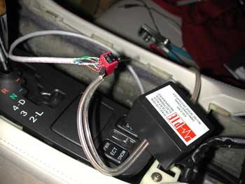
-
Added Line Level Audio Input To Sc430
guykuo replied to guykuo's topic in Audio / Video / Electronics Forums
Audio of head unit can be intercepted at this molex connector. No need to pull the head unit. The left molex connector is the one of interest. It is the one with cat 5e wire spliced in to carry the audio signals from head unit and audio input lines of ML amp to 4PDT switch. Be sure to resecure and loom the wiring. The audio signals in the system are normally differential format (balanced) so each channel as a + and - signal carrier. The shield line is the signal ground. This posed problem because my MP3 player as unbalanced (RCA style ) audio output. A DC blocker allowed feeding of the unbalanced signal to the + and - phase signal wires of each channel. I suspect the video lines of the navigator also pass through this area. Might be possible to intercept and add a video input for the navigator screen here as well. It would certainly be easier than pulling the Nav display out to access its connections.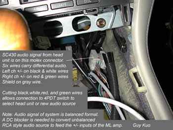
-
I've wanted to add a good line level input to my SC430's Mark Levinson system ever since getting my car, but nobody seemed to have a good solution. I haven't found a single aftermarket adapter for the SC430. Then, I found a little tidbit and contacted Rocky Livingston because he seemed to have been at least partially successful in this endeavor. Using information and encouragement from Rocky, I opened the SC430 console and gained access to the audio signal harness. I also successfully injected a line level audio signal from my Archos MP3 player. Interestingly I discovered that one doesn't need to pull the head unit to access the audio signal lines. The audio signal and control cables go through a molex connector that is separate from the head unit and lies several inches below the head unit. It is near the right wall of the gear shift console. There are actually two connectors mounted together. The one of interest is the left one with quite a few wires coming out of it. Accessing the signal lines there means I don't need to pull the head unit. Only the wood panel/cup holder assembly need be removed. Lacking a schematic, I coudn't totally verify my findings but, I believe I have narrowed down the left and right channel signals to the black/white (right) and red/green (left) wire pairs and a gray shield wire on the connector. Indeed, tapping the signal lines and injection of audio lets me pick up or inject audio into the Mark Levinson system. The signals appear to be balanced format with the red and green wires carrying the left channel, while the black and white wires carry the right channel. Direct injection definitely creates clearer audio than my cassette adapter, albeit softer. As Rocky indicated to me, the volume, fader, and other functions of the ML amplifier are controlled by other control wires in the harness. Substitution of another audio signal by splicing into the audio signal lines leaves the controls active. I can actually adjust balance, volume etc. normally on the head unit while listening to my injected audio signal. Once I build a suitable switching mechanism to transfer the four signal wires between the normal head unit output vs the mp3 player output, I should be able to simply set my switch to select the MP3 player and use the head unit controls as usual. The head unit will simply play its selected source, but the ML processor/amp will instead receive the line level signal of my MP3 player. My next task was to build a suitable means of selecting a new source input and converting the unbalanced output of my MP3 player to properly feed the balanced input of the ML system. I used a 4 pole double throw switch and a PIE DC blocker to do the trick. It worked! I cut the four audio lines and hooked up a 4 pole double throw switch to let me select between the head unit and signal from a PIE DC blocker. The four lines (Left+, Left-, Right+, Right-) lines to the amp were connected to the switch's center poles. The corresponding lines from the head end connect to their mates with the switch in one position. In the other position the four lines to the amp are connected to the shield and pin lines of the DC blocker. No more need for a cassette adapter! Frequency response and dynamic range are much improved. No more tape adapter hiss or clackety clack of the adapter spinning either! Guy Kuo ------------------------------------------ Below info about opening the console and the signal lines is from Rocky Livingston..... ------- Quote ....Correct, the head unit controls are still fully functional. The audio output from the head unit to the Levinson is 2 channel only. The Levinson unit processes and splits the signals for fader/balance etc… It’s a pretty easy process overall. To disassemble the console: 1. Start by lifting the center storage compartment lid and remove the seat heater controls. Press forward on the heater control piece from inside the storage compartment. It easily pops right out. 2. Then set the parking brake and move the gear shifter to neutral. 3. Starting at the seat heater control location, pop out the wood grain assembly on the center console. You will need to disconnect one or two light connectors connected to the assembly to fully remove it. 4. Pop out the wood grain assembly surrounding he head unit. This gets a little tricky because of some of power lid and ash tray wiring, but it’s still pretty easy to remove… 5. Now you should have easy access to the head unit and remove the 4 bolts holding it in place by using a 10mm socket wrench. You may also need to pop out the AC control assembly which is also simple to do. Just grab it with two hands and rock it back and forth until it pops out. It has 4 molex connectors you will need to disconnect. I don’t remember which 4 head unit leads are audio. I downloaded a schematic off the net to figure out all this stuff… Unfortunately I’m not sure where I filed it. --------- end quote ........... The below info about the signal lines is also from Rocky. He did his work by pulling the head unit. I'm doing it at the independent molex connector that doesn't require pulling the head unit. My point of attack means less disassembly than if one tries to do the work at the rear of the head unit. Rocky doesn't mention the signals being balanced format, but they certainly appear to be so from my examination.............. ------------ quote This is a fairly straight forward design. The Pioneer/Toyota head unit, the unit with the with the CD player, has 2 or 3 molex connectors on the rear of the unit. The largest connector, I think it’s the middle one, has a 8 or 10 wires connected to it. 4 of these wires feed audio to the Levinson DSP/Amplifier system, 2 of the wires are a control bus which controls the Levinson sound settings, i.e., Bass, treble, balance, fader, volume… So, you need to insert an external switch, such as the ones made by P.I.E, between the head unit and the Levinson Unit. I don’t have the cable plug pin-out schematic handy so I can’t tell you which leads to intercept. The external switch needs a ground loop isolator installed on it’s output to prevent hum and engine noise interference. You will need to install a power switch somewhere to control the P.I.E. interface. When you energize the power input to the P.I.E., the unit will switch from one audio source to the other. I.e., an external XM radio, MP3 player, external aux audio connector etc….Audio controls from the head unit remain unaffected because the control bus from the head unit to the Levinson are unaffected… ------------------- end quote