al777777
-
Posts
11 -
Joined
-
Last visited
al777777's Achievements
")


-
It's funny that you say what you've said above and yet you have this in your signature ""It should look as if nothing was done at all, should look like it came from the factory that way"". It is because of replies like yours people lose interest in posting anything on Internet forums. I'm no longer interested in doing so. Enjoy your "guru" status. Good bye.
-
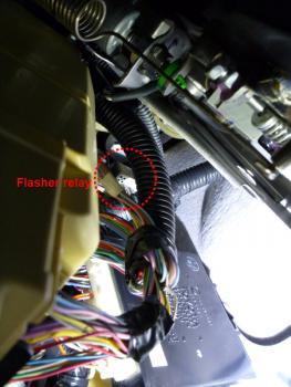
Ok, time for the update (contributing back to the community :-)). This conversion has been completed successfully. For location of the flasher relay on the RX350 - please see attached picture. It is what you will see if you stick your head to under the steering wheel, face up, your head will be touching the edge of the brake pedal. Use a good flashlight. Look up, towards where you think the left audio speaker is. Dotted red cricle on the photo goes around what is the bottom of the relay. Out of the bottom of it sticks the cable connector. To replace the flasher I'd suggest to first disconnect it - feel the latch on the connector with your fingers (it's on the side facing the driver seat. Press it firmly, pull the cable down. I'd suggest not to remove the OEM flasher, instead extend the cable as low as you can, so you will be able to connect/disconnect the LED-compatible flasher without diving head-first - instead you will be able to do it by feel, with one hand under the dashboard. Below is why you will likely need to do it several times. First things first... the LED-compatible flashers seem to be an easy & cheap to procure devices - but with their own quirks. For those who are interested in technical details - they all seem to be based on the LL204 chip (unlike proprietary SE336 chip in the OEM Denso flashers) , LL204 is openly available on the market, specs published on a myriad of Internet pages (Google LL204 datasheet if interested). Typical use of LL204 (by its designers) assumes that control signals ("left/right turn") would be coming in form of a on-board voltage applied to certain input pins. The problem with that is: Toyota's design is to _ground_ certain relay pins to signal left/righ turn. So, our friends in the land of cheap electronics found a workaround, allowing them to build cheap (LL204 based) flashers as a direct replacement of Toyota/Lexus OEM flasher... sort of... as it usually happens. There were two inherent design flaws introduced by them (not blaming LL204 chip makers - the problem is with how it's used). First, Lexus vehicles will lose confirmation flash for doors lock/unlock. Second, both Toyota/Lexus vehicles will experience flashing which not necessarily starts with the lights go bright right at the moment when you push the turn stalk up/down. There may be a small delay, up to as long as the normal flashing's "dark" part of the cycle is. Annoying in my book. I'll not get into more details on these (PM me if interested in technicalities). At least one place that sells LED-compatible Toyota/Lexus flashers claims that they may have a version of it which does not have "confirmation flash" issue. They were out of stock at the time of my research, so I cannot say anything first-hand about that version. And the issue #2 may well be there even if the issue #1 is resolved. These quirks can be fixed, but fixes were time consuming enough for me to start looking at alternatives. So, I bought a used OEM flasher (either 81980-53020 or 81980-50020 will work) and modified it to work with LED bulbs. The easy way is to grind off part of the existing shunt, it's described here: http://vleds.wordpress.com/2010/12/02/how-to-modify-your-flasher-to-work-with-v-leds/ I've found (non-destructive experimental way) that the OEM flasher will not like full normal load from filament bulbs once modified for LEDs. It will behave like it detects an "overload condition" - and it stops flashing completely. I didn't want to do irreversible changes, even to a used OEM flasher (BTW, a new one is ~$120). My modification was to replace the internal shunt with a higher resistance circuit to make it more sensitive and treat lower power consumtion of LED bulbs as normal, thus not hyperflashing. Same principle as with grinding off the OEM shunt, just leaves me with full back-out capabilities. I've started with 0.1 Ohm resistor (actually four of them, made two parallel pairs, then connected them sequentially). I've used four 0.1 Ohm 2W metal film resistors, with parallel+sequential connection it comes back to 0.1 Ohm but with effective dissipated power of 8 watts max. I've then did what may not be an easy task for those who are not in electronics. I've assembled the full schema with actual LED bulbs on my lab table, powered it up, turned the flasher into a left (or right) turn mode - and got hyperflashing. Then I've carefully shaved the metal film surface on one side of each resistor (out of four). In several tries I've reached the point when I'm not getting any hyperflashing between 9 and 15 volts. Disconnect one of the LED bulbs - and it hyperflashes, indicating "bulb out" condition (even though, as I've mentioned in my previous posts this may be of limited value due to how LEDs live and die). Whichever way you will go - without a lab setup you will need to make repeated trips to you vehicle to see if it still hyperflahes, hence having the cable lowered is convenient. Don't forget to test for hyperflashing with both engine off and engine running, I'd even suggect to rev it up a bit while testing to get maximum possible on-board voltage. This is especially important when good LED bulbs are used - they do have constant current LED drivers in them, which means their consumed current actually drops when the voltage goes up, the relay is only looking for the current value (not considering voltage), so you may get no hyperflashing with engine off (12.5 V) and yet have hyperflashing with engine running (13.5-14V). Anyway it all was a successful exercise, I'm happy with the results. For those who will be tempted to quickly write this approach off as too complex when compared with use of powerful load resistors - please do it at your own risk and if you can - please refrain from advertising load resistors method to others. I know it works, probably flawlessly in a 100 cases of proper installation, but it takes one wrong case to have a tragedy. Think about under-rated (power-wise) and/or wrongly placed load resistor setting a fire in a vehicle left with a child inside (and four-way flashers on - for safety!). Yes, I know we're not supposed to ever leave a child inside a car alone, so it never happens, right?.. Thanks for understanding. I just wanted to contribute back to this forum. Thanks for reading. Al.
-
Thanks for the reply! Maybe due to the length of this trail the original question/proposition got lost between the lines... I'd like to summarize it here: 1. LED bulbs go into all four flasher housings. 2. Factory flasher relay gets pulled out of its socket, a replacement relay goes in (please see my previous posts on how to get it for ~$15, if interested). 3. It's done. I don't see how the relay replacement is "messing with the factory relay". If anything, splicing factory wiring harness (or using insulation-piercing clip-ons) is messing. Also I don't see how unplug/plug operation is more work than installing four new elements. I do believe that while load resistors work - they are not an elegant engineering solution. Besides, should something bad like under-hood fire happen (for totally unrelated reasons) - try explaining your insurance company what 4 heaters were doing in the car. Those four load resistors when under load are equivalent of a small soldering iron, each. The only question I had (and still have) is how to reach the Relay Block No.1 to replace the flasher relay with "LED-compatible" one. Nobody seem to have the answer. Maybe it's time to simply put this topic on hold. I'll post updates if/when I'll complete this mini-project. Thanks to all who replied! Al.
-
:-) Sorry for being too technical... :-) I've sent a PM to our fellow member ("cduluk") - maybe he had some experience with that part of 2nd Gen RX... Al.
-
Yep, that will work for cases where a catastrophic failure happened to the LED bulb, such as dead driver circuit or in a simple LED bulb - one of LEDs in the chain have failed open. When I've said "effective detection" I meant detection of all cases, including gradual deterioration (probably heat-induced) of LEDs. In the latter case it may end up with the almost the same consumed current but dramatically lower light output. Current sensing method will not detect that condition. Al.
-
Thanks for the diagram. Yup, I've got the same one, same approximate location. As for the "can't expect" - we can always hope :-). I just have time before the ordered parts will arrive - so I have time for "hoping" :-). Once the parts will arrive - there will be time for "suck it up" :-). Thanks again! Al.
-
Thanks, Paul A. ! This is my fifth message, will see if it unlocks me for sending PMs :-). Al.
-
Technically correct approach. We're lucky though - no need to do any modifications, for about $10-15 we (Lexus/Toyota owners) can get already adapted plug'n'play replacement flasher relay. Just search on ebay for "Toyota LED flasher" - there will be a bunch of offerings, with part number "81980-50030". It is a direct repalcement - remove the OEM one, plug in the replacement. A note: it does flash at normal rate for any combination of LEDs / filament bulbs, including all filaments and all LEDs; and a side effect of it - there will be no "hyperflashing" notification even if one of the bulbs will go out. Because of it I'd recommend to use it for full LED conversion cases only - properly designed and installed LED bulbs will last very long time, and besides when LED bulbs die they will not necessarily drop their consumed current to zero, so effective detection of failed LED bulb is difficult if possible at all anyway. My original question still stands - does anyone know how to reach the flasher relay in 2008 RX350? Many thanks! Al.
-
No crawl yet - don't want to start disassembling the dashboard until I have the relay (it's in the mail, like LEDs). Borescope is a good idea. Thanks. As for the "why" - we can get into a lot of philosophical discussions, but I'll just stick to physics and a bit of psychology . Stop lights - LEDs are useful, everybody agrees. But I'd argue that it's not so much / not only because of the "ramp up time" of a filament bulb vs nearly instant LED's Off-to-On transition. In my opinion it has a psychological factor in it - human eyes (brain actually) are more alerted to fast moving/fast changing objects. Our DNAs are carrying it from our history - those who weren't reacting quick enough to something fast-moving... well we're not their descendants I'd say :-). So, fast changing "something" makes human brain treat it as a higher priority event. Let's say you're dealing with some messy live wiring (not recommended :-)) and all of a sudden something starts glowing in the middle of it. You probably will quickly come to conclusion that something got shorted and will promptly withdraw your hands from it :-). Now, replace that "starts glowing" with "sparked brightly". Don't you see yourself jumping away from it ? :-) The difference is not so much in that you've received a "danger signal" 0.1 seconds faster - it's actually *what* signal you've received. Changing lanes can be just as dangerous as emergency braking, so a bit more attention would certainly help. Have to say though that some of the drivers might as well remove rear view mirrors from their cars as they don't use them anyway, they will not see you even if you'd have focused lasers in your turn signals 8-). That's just my point of view. I respect views of others, so I'm not trying to convince anyone to switch to LEDs. Want to call it "for looks" - I'm fine with that too :-). For those who have read that far - my original question still stands. Thanks! Cheers, Al.
-
Thanks for the reply! I did quite a bit of research/practical work on LED light sources (not just for automotive applications). Unfortunately people often folow the hype of LEDs being brighter than filament bulbs - which is not true... unless you know what to look for on the objective measurements side. Specifically, LEDs are on average 4-5 times more effective than filament bulbs from lumens per watt perspective. So, in case of 7440 bulb (21W) you need LED bulb with equivalent of at least 21/4 = 5.25 W of **actually** consumed power. Note, it's not "rated power" which is often what eBay/other sellers list, it has to be: (13,5V x bulb current) = has to be not less than 5.25W. Some of Ebay sellers often quote something like "11 watts" - but ask them where all the heat goes... LEDs are more effective than filaments, but NOT 100% effective - even the most effective ones release larger part of supplied power as heat and not as light - and they are much more sensitive to heat, compared to filaments. Eleven watts and tiny aluminum ring as a heatsink... buy it, measure, actual will likely be 1...2 watts. Most of people buy, install and end up either throwing them away (good move!) or drive around with dangerously weak lights. This is a "rule of thumb" to start only, a "not less than that" rule. Then more efficiencies can be derived from choosing/building (did both on many occasions) LED bulbs with proper light distribution pattern to match what your light housing is calling for (it will never be ideal though, just like with "HID kits" in housings for halogen bulbs). Regular bulb is considered to be a lambertian ligth source ("a dot emitting light in all directions", sphere of light pretty much). LEDs emit all of their light in one direction, with anywhere between let's say 20 degrees and 180 degrees aperture. Some of the regular bulb's light emission is lost (e.g. the part that hits bulb's socket). LED bulbs **can** be made to not have that loss of light. Then there is a fact that colored (amber in this case) bulbs have their output severely affected by the fact that the color filter is basically a rejection filter - cutting out everything from the white(ish) filament spectrum except the needed resulting color, the rest turns into heating of the bulb's glass. LEDs emit the color you need from the beginning, which is great for RX case as we have clear light housings, (almost) no additional loss there. With that in mind, selection of (The Real) LED bulbs becomes much more meaningful... and much more limited. I guess it would be against the forum rules to mention exactly which product I'm planning to install (can be considered advertisement), but I can say that the bulbs I'm planning to put in have actual measured 5 watts draw for the front (each) and actual 6 watts for the rear. Fronts will be "front-shooting" Cree-based devices with light distribution lenses (this is supported by the shape of RX's front turn signal housing - longtitudal, elongated with the bulb in its deep end). For the rear it will be a module with 5-way firing high-power SMT leds (not an average 5050's!), 6 watts of actual draw. All four have constant current drivers in them (not the eBay-style chain of LEDs with a resistor). I totally agree with banning weak-looking self-installed LEDs - they are plain dangerous. And once I'll try this setup on my RX (LEDs are in the mail now) - I'll be making a decision based on how bright they are as a system - i.e. in the housing, flashing in the broad day light. If not as bright as stock - off they go (and then I don't need to disassemble the dash :-)). Now, to those LED bulbs you've mentioned - not to bash on the party offering them, but couple of notes: 1. Built-in resistors are still mini-heaters, we all have seen soldering irons which are let's say 25 watts of power - well, the resistors in that bulb would have to dissipate close to 20 watts to simulate the original bulb. By look of them they're likely a ceramic surface-mount kind, so likely nothing will melt and hopefully they will not desolder themselves over time. But still, an engineer deep inside of of me tells me that roasting LED chips with closely located heater is not a good idea. 2. These bulbs look like they have 21 SMT leds (looks like typical 5050 surface-mount, three-chip LEDs). Direct voltage on each is about 2 V (for amber/red color ones), typical recommended current is 0.06A which comes to 0.12W per each 5050, multiply it by 21 = 2.52 watts. It certainly will look cool at night... you know how it would look in the day light... These LEDs can be driven twice harder (absolute maximum current is 0.15A) - sounds like ~5W is achievable, but I doubt its longevity in that case (doesn't look like they have any constant current driving circuits, plus those "heaters" nearby...). Thanks for reading this long post. And to all - I'm still looking for instructions on how to get to the flasher relay in RX350... Please let me (and everybody!) know if you know how - thanks! Al.
-
Hello everybody, I've searched left and right and it seems that no info was ever posted on this topic... I'm planning to put LED bulbs into turn signals in my 2008 RX350. Part of the process (and to avoid having load resistors hanging of four corners of the vehicle) is to install LED-compatible turn signal flasher relay which is a direct plug'n'play replacement to the OEM relay. This is to prevent "hyper-flashing" effect - with OEM relay I'd get three-times faster flashing turn signals (because LEDs consume less power - OEM relay "thinks" that a bulb is out). I've found a diagram on the Net, looks like on RX330/350 location of the flasher relay is different compared with RX300. In RX300 it was accessible from under the steering wheel area - drop the cover(s) and you get access to a large panel with fuses, the flasher relay hangs close to it's right side. In RX330/RX350 it looks like the flasher is on a separate "Relay Block No.1" which is buried somewhere deep in the dash, on the left, behind the left AC/heating vent, looks like it is close to the engine compartment firewall. That is unless I'm misreading that diagram. Question: Would anyone happen to have instructions on how to get access to replace the flasher relay in 2008 RX350? Really don't want to get into disassembling half of the dash just to get to it... Hope there is an easier way... Many thanks for reading this! Al.