


Peter2000
-
Posts
4 -
Joined
-
Last visited
Content Type
Profiles
Forums
Events
Gallery
Store
Articles
Videos
News & Articles
Posts posted by Peter2000
-
-
I just installed on my 200 GS400 a new aftermarket navigation Pioneer AVIC8200NEX and used stock Amplifier and stock speakers.
Stock HU unit, Navigation and CD changer has been removed.Simple stock amplifier's hardware modification required.
Problem with using stock amplifier has been solved.
If you like know more about it, please drop a line to me.-
 1
1
-
-
Did you scan for any error codes?
I will suggest to check your PPS (pedal position sensor).
-
Code P1120 is code for malfunction of APPS (Accelerator Pedal Position Sensor).
This pedal position sensor (APPS) have a dual output inverse of each
other, a redundancy for safety reasons.
Cost of sensor on line ($270, at Lexus $400)Be aware, there are two sensors on throttle body.
First one (closer to front of vehicle) is for throttle servo motor (don’t
touch it!).Second one (closer to firewall) with accelerator pedal cable attached to it
is one what causing the problem.
I replace several of those APPS sensors.Because I'm specializing in automotive electronics troubleshooting, I took
all of them a part.By doing so, I discovered on all of them common
problem, what fortunately is an easy fix.
Malfunction of that sensor is caused by improper cleaning of organic solder
residue during manufacturing of sensor.
This organic solder is very aggressive and after years of exposing this
solder to harsh environment, acid in that solder causing self-destruction of
solder what result of it is so called "cold
connection".
Manufacturer ignored (perhaps intentionally) basic rule about cleaning
contacts after soldering and
protect it against moisture by covering soldered area with some kind of
protective layer what is very common in automotive industry (shame on
Toyota).SOLUTION:
Fix is very easy and can be done in less than hour include dismount and
mount of sensor.
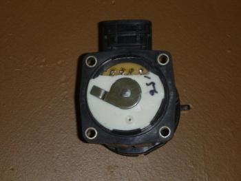
To do so, just make small opening in to white plastic cover at location where
is connector (see my picture).By creating opening, you will create access to soldering points.
VERY IMPORTANT!!!
Apply new solder to existing points and take it all out (use desoldering
tool or cupper mash to do so).By doing this you will remove old solder and expose contact from connector.
Now you MUST clean those contacts by using very sharp knife and scrape old oxide
layer from those contacts.To verify if you did good cleaning, you will see after scraping nice shiny
brace contacts. Second verification is, that when you apply new solder on those
contacts, it will perfectly cover it with solder. If you will see solder
creating small ball and not covering entire contact, you need repeat process
again till you get perfect join solder to contacts.Next step is just nicely resolder all 4 contact to PC board with non-organic
solder (best is solder with Resin flux), but if you don't have solder with
Resin flux, you can use solder with organic flux (same as Toyota used) but you
will have to use warm water to clean soldering points to remove any organic
residue to prevent from same mistake as Toyota did in first place.After drying up inside soldered area (use hair dryer) to prevent from
moisture entering in to this part, you must cover opening (in white plastic)
with good tape or any kind of non-conductive sealant (best is clear non-conductive
silicone).If you use silicone to cover opening, be very careful do not overfill inside
opening, otherwise you will create restriction for potentiometer to freely
move.After silicone dry up, you can install your APPS and enjoy it.
If you did good job, you will not have problem with this part for entire
life of that car.If you have any question, you can e-mail me at: sekcov@yahoo.com
Peter


Problems After Replacing Front Power Window Actuators
in 93 - 05 Lexus GS300 / GS400 / GS430
Posted
I like to share my experience with replacing door locks on my 2000 GS400.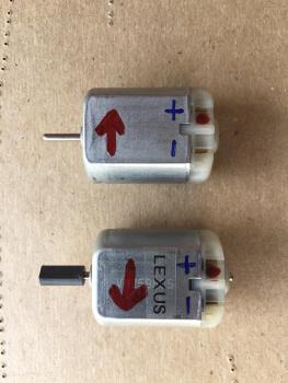
I decided to replace all my door locks actuators by purchasing after market set of 4 for all my doors.
After install rear doors, actuators worked just couple of cycles and stuck (chines junk).
Than I returned my old rear actuators and continue to replacing front actuators.
Those aftermarket actuators had hard time to fit. I had to shave some p[plastic material from white lever, because was hitting bracket.
Than I had to put 1/16" spacer under actuator to accommodate free movement of levers.
After that, my front actuators seems to work OK, but not for very long time.
Next day i discovered my car acts weird during locking and unlocking.
Every time when I unlocked my door, door locks cycled twice.
Sometime if I opened door before second cycle, my alarm has been activated.
By investigating problem I found that both front actuators did not have (apparently) internal switch call "Lock detect".
By measuring Front Left (driver side) lock actuator connector Pin#3 and Pin#4, there was no short when door has been locked.
I got very upset and removed both front actuators and returned to seller on E-bay.
My next step was to purchase just motors to replace them in my original actuators.
After my motors and pulley remover arrived i performed motors replacement.
Opening of actuators was not that hard, just very important step on beginning when you have to start make a crack by inserting box cutter knife. Than I used flat screw driver and was cracking glued area from inside out. (better if actuator is cold or frozen).
After my successful motor replacement and installation door locks in my car, another problem occurred. (why not).
My door locks functioned exactly opposite as they should work.
When I pressed Unlock, my car locked and vice versa.
By comparing Toyota (old) motor with new replacement, i discovered, that new motor rotation is CCW, but original Toyota motor rotation is CW.
This was easy fix. Just swapped motor wires inside each door door lock's connector.
Now all is working as suppose to.