osucool
-
Posts
24 -
Joined
-
Last visited
osucool's Achievements
")


-
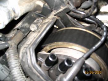
The wire(s) are viewable from the top.....they are the ones that you can see that seem to drift off into the compressor pulley. One of these wires comes out and is grounded to the Black painted bracket with philips head screw. Two screws are used to attach the bracket to the compressor. To remove these two screws You will probably need to release the cable clip as I think it clips into the bracket, from memory. Clean the connection points between this wire connector and the bracket and between this bracket and the compressor. Re-install the two philips head screws and reclip the cable run. Hopefully this works for you (or someone) as well.
-
Really Wierd Tire Wear After Multiple Alignments
osucool replied to Airtraffic's topic in 92 - 00 Lexus SC300 / SC400
I too had a pair of Kumho Tires that had some excessive outside wear a few years back. It seems there is a range of alignment acceptability according to the folks at the tire shop. They said something like...."we normally shoot for the ?negative? camber side of this range and it will give you a more sportier feel." I mentioned (firmly) that the tires were just a few months old and the outside tread was half gone and they re-aligned it. I do not drive the car much but there is at least another 20,000 on it since then and a few years later with acceptable wear. Not sure if I can dig up the numbers they gave. It was inside the tolerance range before and after. My opinion: #1 Kumho's wear pretty fast in general especially when they are not happy. #2 If you go back in...have them print off the actual number values where they are setting them along with the allowable range they shoot for. If they have a fancy Hunter machine they should be able to. At least you can publish your alignment numbers or have them adjusted until you are good with the wear pattern. I'm no tire expert but it sure seemed to help for my car. -
Over the past few years this problem has come a back few times. Each time I mess with the wires and everything is fixed. The probem I now realize is corrosion on the wire connector....The ring connector that attaches the one wire to the compressor body. I believe this wire is the ground path and not making good connections. Upon cleaning the connector and the bracket and re-install this fixes everything. Hopefully this will further help other folks with similar issues down the road. Do this before replacing your compressor.
-
I would try an ebay key specifically for the SC400. I think you can seperate the new key and use the plastic portion with your existing old metal portion of the key. It has been a while since I looked at the internals of the SC400 key so you should get a second opinion, ask dealer etc..
-
Driveshaft Donuts/bearing Replacement?
osucool replied to Graham's topic in 92 - 00 Lexus SC300 / SC400
Mine sounded that way too so I changed the intermediate bearing, no change. Its pricey too. I swapped the driveshaft for a better one I picked up with an ebay engine ....less slop in the interchange portion and much better rubber, but little change. The simple answer. Transmission mount was the issue. Changed it for a new one and its all smoothed out no noises on decelleration. -
#1 You are going to the wrong school at least for Basketball this week. Seriously..... Go to autozone and get you a mityvac vacuum pump and do the fluid bleed procedure from the abs bleed fitting. Mine does this periodically...maybe moisture in the fluid or other.
-
Answering myself again. I never found the Steering ECU , Supposed to be under the dash on the drivers side, lots of good things there but no Steering ECU at least for My SC400. While I have been messing around looking for a few days, my Steering solenoid valve (screen portion) was soaking in some sea foam. Also I ended up replaced the Oring that is on the end of this soleniod valve. Either one of these may have helped enough to bring me back to easier jerk free steering.
-
Situation to analyze for anyone with steering system knowledge. Steering seems fine at low speeds, maybe a tad harder than necessary. Steering somewhat difficult at higher speeds. Making a tighter turn at higher speeds gives a pulsing jerking motion (not cool) Car has done it since I got it in 2003 I have recently began to dig around on the car more so.... New power steering pump last month. Have cleaned the solenoid valve in the past year, not much better but the pulse-jerk was less pronounced. Would a new solenoid valve cure this issue ? I may try to clean it again but I wanted to ask before I get the vise grips out. (Ohms were good last time, but valve screen very dirty) Any advice on the type of cleaner to use for best results? Is there any way the Steering ECU is the culprit here? I would test it if I could get confirmation on the location. Any help appreciated
-
After looking at valve timing, injectors and throttle body. I am trying to get back some lost power that may be caused by clogged converter(s). Does anyone have the resources to measure exhaust airflow for a stock SC400 (1992) ? I think I can use a hand-held airflow meter (from my workplace) placed at a fixed distance from the exhaust and get a Feet per minute measurement for airflow - for different RPM's. I have a feeling mine may be less than ideal but need a good comparison. If anyone has the resources let me know. (I wonder also if my local emissions place could give this data) Thanks in advance for any input. ps. If you think your high flow exhaust is better than another this would also be good info.
-
Valve Shims, Pain In The Butt To Remove Far End Shim.
osucool replied to osucool's topic in 92 - 00 Lexus SC300 / SC400
OK, I am answering myself again, Some words of advice after I have success with the valve shim swap. 1.) The standard issue valve tools are kind of cheap but they do ~ function. I was too harsh on them previously 2.) Find a suitable spot for the cam lobe so it does not interfere with the compressor tool. 3.) Before compressing, Locate the shim hole in a spot where you can get your air nozzle. (see #12) 4.) When you are deciding which end of the spacer tool to use Keep in mind , it is OK to use the smaller end. Really. 5.) When you think your spacer tool is in the right place, it is - when you can move the shim but not the valve. (Try again) 6.) After you remove a shim do not even think about removing the spacer tool unless you have a very easy spot. 7.) If your spacer tool slips out you will spend some hours trying to re-establish a good position on the edge of the valve that will not interfere with the shim-reinstall. (Unless you are on an engine stand with direct sight or you have one of the valves that are more easily accessible) 8.) If you happen to think you can rotate the engine with the shim removed, you can, but you will spend countless hours trying to remove the burr you created as the Cam Lobe moved over the edge of the un compressed valve where the shim is supposed to be. My Ebay spare motor (on the stand I was using as a test subject) may now be questionable with some shavings created. 9.) Stuff some rags in the spots where the shim may fly out and never come back from. 10.) Make sure your magnet is good enough to hold the shim by itself. 11.) Make sure you have a good mirror & lights. 12.) Get an air nozzle set up that will fit down into, yes into, the hole on the shim. I used a standard air gun nozzle connected to a rubber vacuum hose and a vacuum fitting with a very small nozzle that would fit into the shim hole. 13.) I found it very helpful to have a small hook tool that could insert into the hole. (.062 rod - bend the end at 90deg - as short a bend as possible) Hopefully this long rambling will help some other soul that feels the need to adjust their own valves. It is a piece of Cake. Not sure what kind though. -
Valve Shims, Pain In The Butt To Remove Far End Shim.
osucool replied to osucool's topic in 92 - 00 Lexus SC300 / SC400
Thanks for the link, that is what I have. A very good representation of the timing marks as well. They make it look so easy with Special Service Tools SST A & SST B. I wonder: Has anyone used these with Success. Has anyone successfully re-installed a shim after using these. They tend to create a burr which interferes with shim install. -
Does anyone have any words of wisdom for Valve Clearance Shim removal? I have one valve that needs a new shim. (An Intake Valve measuring .013 clearance ) Its The one on drivers side nearest the firewall. I have successfully removed this shim on my spare engine which is on an engine stand but even when it is completely out in the open it is still a pain in the butt to get the spacer tool to rest on the edge of the valve tappet. I know what needs to happen but I can't get lucky with this Toyota-Lexus Shim Removal set. I created a small fish hook looking piece to grab the hole in the shim to help removal but with the engine in the car this is a rough job to free up the shim. Is there another easy way (bearing cap removal ....etc) or any other method that may help. After struggling with the engine in the car I am tempted to seal valve covers back up and live with it before I screw up a cam lobe or something. Words of advice are welcomed. Thanks
-
Sorry, I think I answered my own questions and I am set correctly. Timing Marks line up every two turns (2x360deg). Timing Fixed Marks are present as an embossing on the metal brackets behind the timing belt sprocket. Timing Rotating Marks are present as slits on the visible OD of the camshaft sprocket. (about the size of a small flathead screwdriver ~1/16" deep) Crankshaft white mark aligned on the 0 when #1 cylinder is at TDC and compression stroke. Picture attached shows location of fixed timing mark. Middle of screen, white dot of paint. Mitchel Service manual shows it in more detail correctly. Good luck to the guy who needs to reset.
-
I too have a similar issue for the SC400, I have recently had a radiator problemand decided to check into the timing. The SC400 Service manual I have gives a good picture and procedure for the Inline 6 but fails to detail a V8. I do not see a dot on the crankshaft. Where would this be in relation to the white Timing Mark? I have looked closely. I see two things happening on the Camshaft sprockets, a line mark on the outside and a protruding tab from the sprocket. IF there is a dot on this can you define its size? Also, with each turn of the crankshaft I seem to have a different configuration, I may be able to do this indefinitely. Should this fall in the same position every xxx turns? I would like to just pull the belt and start competely over but without a good guide for setting it this might be a long process. When I posted something on this subject a number of years back I think I was at 14BTDC with my timing and it has always ran so-so . Anything you can further add would be appreciated.
-
While I am waiting for Monday to come around, more questions maybe the experts can answer.. If a timing belt is off by one notch does anyone know the probable effect on the timing? I would think more of a difference than a few degrees of Crank angle. One notch on the crackshaft gear = ?? degrees One notch on either of the Cam gears = ?? degrees IF anyone has the number of teeth present on these gears I may be able to work this out. OR Would out of adjustment valves cause the computer to do this compensation? I appreciate the help.